 |
|
HOME > Technical Information > Switches, PBX's, and Central Offices > Chapter 9 |
This chapter is also available for
downloading. Please choose Word 97 format
or plain text and download the images for this chapter which are contained
in the files images9.zip.
| Chapter 9 in Microsoft Word 97 format click here. |
Chapter 9 in plain text format click here. |
Chapter 9 images contained in zip file format : images9.zip |
CROSSBAR TANDEM
One of the most cherished of American traditions is that of the hired man. He did
anything-sharpened the lawn mower, sprayed the apple trees, removed water from the
carburetor, varnished the go-cart-whatever he was asked to do. The Bell System has a
pretty good "hired man" in crossbar tandem. It was not meant to be a
"jack-of-all-trades" (in fact, some people thought it would be limited largely
to New York City) but, as a factor in the growth of extended-area customer dialing and the
implementation of direct distance dialing (DDD), it has had to take on one new job after
another. New features added as the needs developed give it a versatility undreamed of in
the 1930's.
Tandem offices handle essentially trunk-to-trunk traffic, usually with fairly high calling rates because the trunk groups carry traffic that has been concentrated from low calling-rate customer lines in the originating local office. Tandem systems are not suitable for the switching of traffic submitted directly from customer lines.
Originally, the crossbar tandem system accepted only incoming revertive pulsing because that satisfied the requirements at the time. The chief advantage was in the varieties of outpulsing, because the common-control circuits permitted outpulsing to panel, crossbar, or step-by-step local dial offices in addition to completion to manual offices. Shortly after the initial installation, a demand arose for an arrangement to permit dial pulsing into crossbar tandem by operators from switchboard positions in the same city. An incoming dial-, pulse sender was developed to satisfy this need, and it later proved adaptable without change for dial pulsing from inward toll lines.
The next step in the evolution of crossbar tandem was forced by the enormous postwar growth in toll business that threatened to swamp both the No. 4 toll switching systems and the manual toll systems that had not yet been replaced by No. 4. The development of an incoming multi-frequency (MF) sender to permit crossbar tandem to accept MF signals was easily justified by the wide usage of MF pulsing, and quick relief was realized, particularly in the larger, more heavily overloaded cities.
For example, Gotham tandem, in New York City, has more than 3,000 incoming toll trunks. These represent calls that could not have been dialed at all because the New York No. 4 system was at full capacity. All these trunks would have had to stay on the manual inward toll switchboards with operating penalties. Another No. 4 could have been started but, at the time, production facilities were hard pressed and the No. 4 systems being manufactured were urgently needed elsewhere.
In Washington, D. C., with no toll dial system available for 2 to 3 years, crossbar tandem was arranged to serve outward toll calls requiring dial pulses. The required features were already in the dial-pulse sender and no development was needed other than fitting existing building blocks together. However, the outward digit capacity was limited to 6 digits.
Multi-frequency outpulsing, of course, was under development and is now available. This expands the field of use of crossbar tandem for inward and outward switching and also for through switching where transmission considerations permit.
About 80 crossbar tandem systems are now in service. They are serving the original need for having trunks on local-to-local business, they are handling remote-control zone registration, and they can carry tremendous double-tandem loads such as the San Francisco-Oakland cross-bay traffic.
The versatility of crossbar tandem is well illustrated by the multiplicity of inpulsing and outpulsing "languages" now possible, Table 1. PCI (panel call indicator) was designed to provide changes in both polarity and amplitude of signaling pulses. DP (dial pulsing) is a decimal counting scheme where each digit is represented by a number of identical pulses equal to the numerical value. RP (revertive pulsing) combines arbitrarily-chosen groups of pulses into the office code. The thousands and hundreds digits are sent in a manner referred to as "brush" and "group". After another brush selection, the tens and units digits are sent. MF (multi-frequency pulsing) is sent by two simultaneous pulses out of five possible frequencies. Start-pulsing and end-pulsing signals are also required. MF is the fastest, about one second for seven digits; PCI is next, about three seconds; and the other two methods take about seven seconds each.
TABLE I - CHARACTERISTICS OF
PULSING LANGUAGES
Pulsing Rate
Type of Pulsing Characteristics (Digits per Second)
Dial Pulsing Decimal; counted by open and closed Average I* contacts in loop.
Revertive Pulsing Coded non-decimal and decimal; open Average 1-2* and closed contacts in terminating office; counted in originating office.
PCI Pulsing Variations in voltage and polarity. Invariable 2.9
MF Pulsing Two out of five voice-frequency tones. Maximum 7*
'Machine time. Humans (customer or operator) may be slower.
Possibly the most important aspect of crossbar tandem is its use in centralized automatic
message accounting (CAMA). In this arrangement, the necessary equipment to record billing
data for automatic message accounting (AMA), centrally located at a crossbar tandem
office,-serves up to 200 local offices. These local offices thus get the benefits of AMA
without the need for a considerable amount of additional equipment in each local office.
Crossbar tandem offices permit such an arrangement. The latest development is an
arrangement whereby step-by-step offices will be provided with CAMA service. This has been
made possible by a new CAMA dial-pulse incoming sender for crossbar tandem, to work with
the step-by-step equipment in local offices.
Under development at present and expected to be installed in the near future is a new multi-frequency (MF) incoming sender to permit CAMA operation of local offices that can outpulse MF signals. Closely allied with this development is the feature of automatic calling-line identification. This is expected to be developed within a few years. It will provide full automatic CAMA operation of panel and crossbar offices equipped to outpulse MF signals, so that an operator will no longer have to intervene on each call to determine verbally the calling telephone's number.
Equipment Arrangement
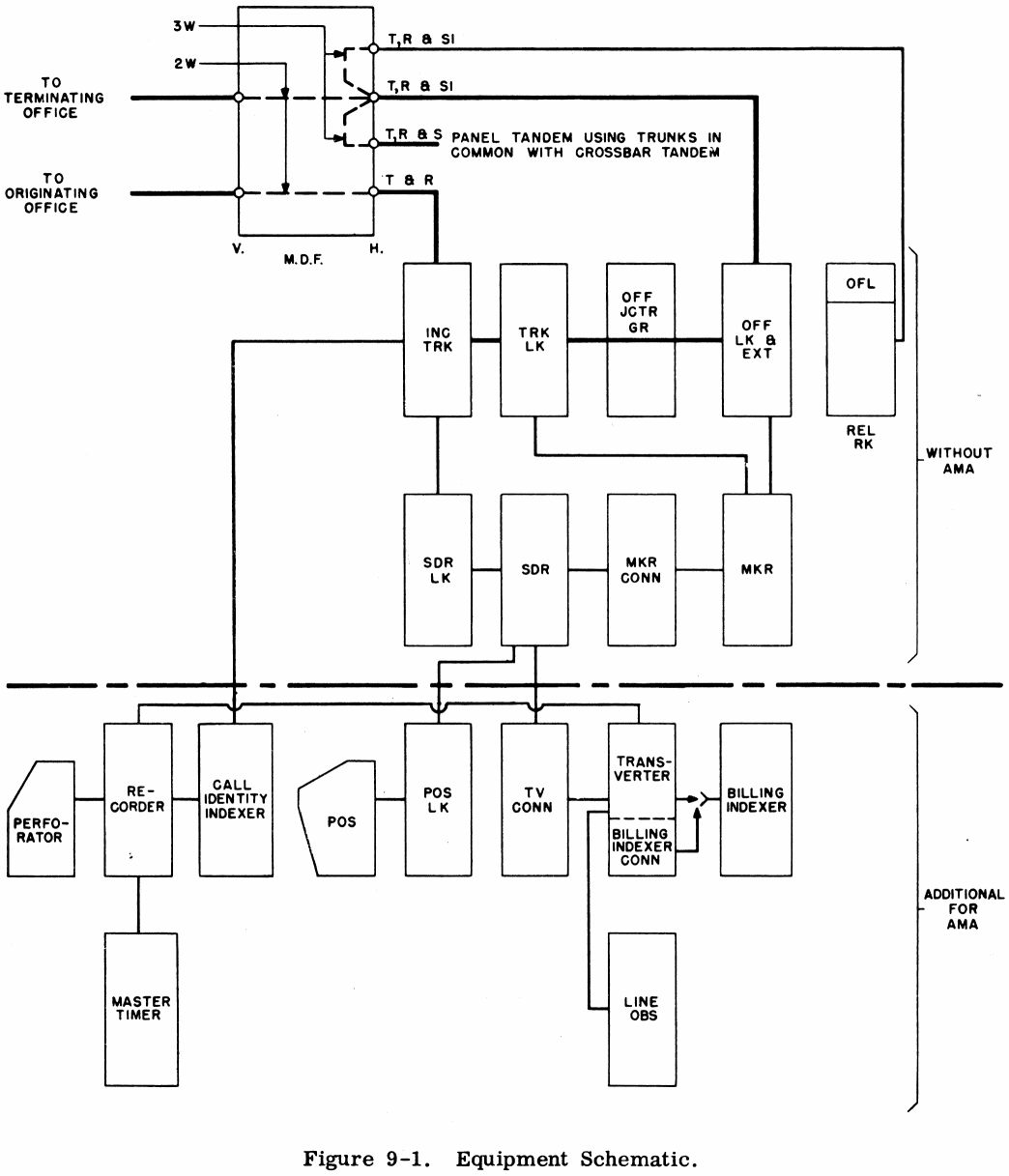
In operation the crossbar tandem system functions in many respects like a local crossbar office. As shown in Figure 9-1 the incoming trunks connect through the trunk link frame, office junctor grouping frame, office link frame and outgoing trunks to terminating equipment in other offices. The trunks become associated with tandem senders through the action of sender link frames. The senders receive their registration. from the distant office on a revertive pulse, dial pulse, multi-frequency pulse or panel call indicator pulse basis. The senders control the tandem selections and the selections beyond. The markers which route the call through the tandem equipment under control of the tandem sender registration are associated with the senders through the marker connector frames.
The provision of CAMA equipment in the tandem office does not change the fundamental plan of completing calls. It does, however, as shown in Figure 9-1 involve the addition of a number of other functions and frames to obtain the data for billing the calls.
The elements of the CAMA calls which are recorded for billing purposes include the called and calling subscriber's number, the time of answer, time of disconnect, called area, calling office and message billing indices and the trunk number. With the exception of the calling subscriber's number all these factors are either known as soon as dialing is completed or derived during the process of the call. To obtain the calling subscriber's number an operator is called in during the setting-up process of the call and keys the number into the sender before the call is allowed to complete.
The equipment added for CAMA operation consists of the switchboard, position relay equipment, perforator, position link, transverter, master timer transverter connector, billing indexer, recorder, call identity indexer and certain maintenance frames.
Equipment Description
Trunks - There are a number of types of incoming trunks in a XBT office.
Remote control zone registration trunks are used for handling calls from panel offices arranged for remote control zone registration. Supervision is repeated in the trunk and charging pulses from a 170 volt supply are sent to the originating office on a simplex basis according to the rate cross-connection in the trunk and duration of the call.
Through supervision trunks are used for completing calls between offices when the supervisory loop set-up between the calling office through the XBT to the called office is within the range of both offices.
Repeated supervision trunks are used when the supervisory loop is beyond the range of the offices and must be repeated at the XBT.
Simplex or composite supervision trunks are used to handle dial pulse or multi-frequency pulsing and may be arranged to re-ring forward with a simplex ringing signal.
The CAMA traffic is handled over trunks that function the same as non CAMA trunk in establishing a connection through the trunk and office links to the outgoing trunk. After the other elements of the initial entry have been perforated including the calling subscriber's number the trunk identifies itself to the recorder through the call identity indexer causing the trunk number to be perforated as part of the initial entry. After the call is answered the trunk again calls in the recorder to perforate the trunk number again with the answer time entry as is done later with the disconnect time entry. By means of the trunk number the separate elements of the call are brought together in the accounting center for billing purposes.
Trunk Link Frame - This frame consists of a primary and secondary bay of switches and relay equipment comprising 200 links used for interconnection of incoming trunks and office junctors. The primary end will serve 160 trunks and the secondary 200 office junctors. The frame will serve any combination of CAMA and non CAMA trunks limited only by decade requirements and cabling considerations. The number of trunk link frames is limited to twenty by the junctor distribution pattern which also controls the design of the office links and markers.
Sender Link Frame - This frame consists of primary and secondary switches whose function is to connect the incoming trunk to an idle sender. It is a 2 bay frame.. One bay contains four 200 point primary switches, four ZOO point secondary switches, sender subgroup connector multi-contact relays and terminal strips. The other bay contains a fuse panel, trunk group connector (multi-contact 'relays and two controller circuits). The frame serves a maximum of 100 trunks and has access to a maximum of 80 senders.
Sender Frames - These frames are used to mount the sender. The sender controls the tandem selections as well as those beyond. The capacity of the frame varies from 3 to 5 senders dependent upon the type of sender.
Marker Connector Frame - The function of the marker connector is to connect a sender to an idle marker for the selection of a trunk to the proper destination and for translation of the information necessary for completing the call. The frame is a single bay framework with multi-contact relays and associated mounting plate equipment. It is arranged for a maximum of three connectors each serving five senders and eight markers.
Marker Frame - The marker receives information from the sender as to the office code, number of trunk link frame, class of service, etc. It decodes this information and returns to the sender the necessary information for completing the call. At the same time the marker tests for an idle outgoing trunk and establishes a channel from the incoming trunk through the trunk link, office junctor and office link to the outgoing trunk.
The tandem marker is a multi-bay frame accommodating the equipment and wiring for one tandem marker circuit. The equipment consists of plate mounted apparatus, multi-contact relays and cross-connecting fields. The common equipment unit is a two bay frame which may be supplemented by additional bays when additional route relays are required or when more than two classes of service are required.
Office Link Frame - This two bay frame and one bay extension frame are the same as the corresponding frames in the No. 1 local crossbar offices. Its function is to connect the office junctor with the outgoing trunk. The office link frame has a capacity of 200 links the primary switches of which serve 200 office junctors. The secondary switches provide for 100 outgoing trunks if the switches are not split and a maximum of 200 trunks if the horizontal multiples of all switches are a@lit. The extension frame has a capacity of 100 outgoing trunks.
Office Junctor Grouping Frame - This is a 2-bay frame on which are mounted terminal strips and jumper distributing rings used to interconnect the secondary of the trunk link frame with the primary of the office link frames to obtain access of incoming trunks to outgoing trunks.
Office Interrupter Frame - The office interrupter frame is a single bay containing motor driven interrupters used for miscellaneous purposes. For reliability of service, four frames are provided per tandem office and the load equally divided among them.
CAMA Switchboard - On CAMA calls the switchboard is connected to the sender through the position link. The operator obtains the calling number from the subscriber and keys it into the sender. The position is then dropped and the call progresses 'automatically.
The switchboard consists of a number of 2 position sections and a cable turning section. The switchboard section is a low sheet metal structure of the cordless type with a sloping keyshelf. The section has a gray wrinkle finish and the keyshelf has a blue-green color. Each position is equipped with a 10 button keyset, auxiliary lamps and keys. All relay equipment associated with the switchboard is located on a position and telephone unit frame. A maximum of 100 positions per office is possible and growth may be either right or left.
Position Link Frame - The position link serves to connect a CAMA sender to a switchboard position. It is a 2-bay frame which mounts relay equipment and sixteen '5 Wire crossbar switches. The capacity is 40 senders which may be connected to a maximum of 100 positions. Although each frame will accommodate a total of 100 positions a minimum of two frames is always furnished to insure service.
Transverter Frame - The transverter receives from the sender the recorder number, called and calling office codes, rate class and subscriber's number. It obtains the billing index from the billing indexer and passes all of this information to the recorder where it is perforated on the tape as the initial entry. It is a single bay structure arranged to mount equipment consisting mainly of "U" type relays and multi-contact relays.
Billing Indexer Frame - The billing indexer furnishes the billing index number, the office index and type of entry. The billing indexer is composed of a 2-bay originating frame and where required for additional capacity a single bay supplementary frame. Each frame consists mainly of multi-contact relays and cross-connecting type of terminal strip.
Call Identity Indexer Frame - The call identity indexer actuates the recorder to cause the trunk number to be perforated on the tape for the initial entry, at time of answer and at time of disconnect. It is a single bay frame arranged for four indexer units. The call identity indexer is directly associated with the recorder and trunks on the basis of a maximum of 100 trunks per recorder per call identity indexer unit.
Recorder Frame - The recorder is closely associated with the call identity indexer in that each serve the same group of trunks. The recorder receives items of billing information from the transverter, the trunk number from the call identity indexer and perforates this on the tape as the initial entry. Subsequent answer and disconnect entries are perforated with the trunk number. This is a single bay frame on which are mounted four recorder units.
Perforator Cabinet - The perforator used for the final operation of perforating the AMA tape is housed in a sheet metal cabinet each having a capacity of two perforators. These perforators are identical to those used in local AMA offices.
Master Timing Frame - This is a single bay frame arranged for one master timer. Two timing circuits, odd and even, are supplied by the timer with transfer facilities so either can assume the load. Time pulses are supplied every 6 seconds to the recorders for timing, checking and synchronizing. The master timer also provides hour, day and month information when required and causes an end of tape pattern to be perforated daily at 3 A.M.