 |
|
HOME > Technical Information > Switches, PBX's, and Central Offices > Chapter 6 |
This chapter is also available for
downloading. Please choose Word 97 format
or plain text and download the images for this chapter which are contained
in the files images6a.zip,
images6b.zip.
| Chapter 6 in Microsoft Word 97 format click here. |
Chapter 6 in plain text format click here. |
Chapter 6 images contained in zip file format : images6a.zip images6b.zip |
NO. 1 CROSSBAR SYSTEM
The No. 1 Crossbar System uses common selecting features, magnetically operated crossbar
switches and multi-contact relays, built with precious metal contacts to provide
noise-free talking circuits. It is also designed for the efficient use of intra-office and
inter-office trunking based on high usage and alternate routing of traffic by means of its
common control features. The types of selector switches which introduced a high degree of
noise in the panel and step-by-step systems have been eliminated. No power driven
elements, such as are used in the panel system are required.
Since it was expected that this system would be used largely in panel areas revertive pulsing was used for both intra and inter-office calls. In addition, at the time of development, various types of outgoing senders were made available for handling calls to step-by-step tandem and other types of offices as needed.
Automatic recording of messages in the panel system was limited to zone registration. Accordingly the No. 1 Crossbar was designed for the same features using message registers, with a top capacity of five initial register operations. With the later development of Automatic Message Accounting, modification in designs have been made so that No. 1 Crossbar may now be arranged for either method of charging as required.
Some of the more important features, in addition to those mentioned above, are as follows:
a. Use of dual contacts in all talking paths and many signaling paths.
b. Ability to alternate route when initial trunk routes are busy, as well as additional trials when busy's or trouble conditions are encountered.
c. Limited completion of calls to nonconsecutive numbered lines, thus permitting growth in PBX trunk groups without number changes.
d. A single line terminal on a crossbar switch, independent from the call number, serves for both originating and terminating traffic. This permits distributing large PBX assignments over different frames and insuring the balancing of traffic loads.
e. Easy methods of cross-connection to care for change in "first choice" paths, routing to intercepting, etc.
f. A subscriber loop resistance of 1500 ohms including the subscriber's instrument.
Equipment Used in Crossbar
Systems
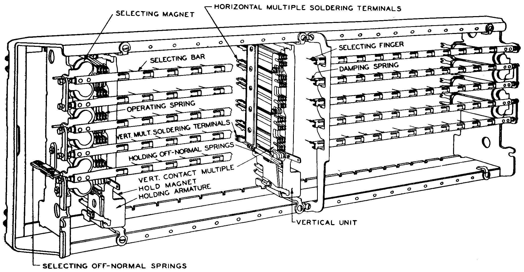
Figure 6-1. Partial Perspective View of 20-Vertical Unit Crossbar Switch (200 Point)
Crossbar Switch - The crossbar switch (Figure 6-1) is the principle line and trunk switching device used in crossbar system talking paths and may be described as a selective multi-unit two stage relay. It consists of a rectangular field of contact springs arranged in ten horizontal rows and either ten or twenty vertical rows. It is operated by horizontal and vertical bars.
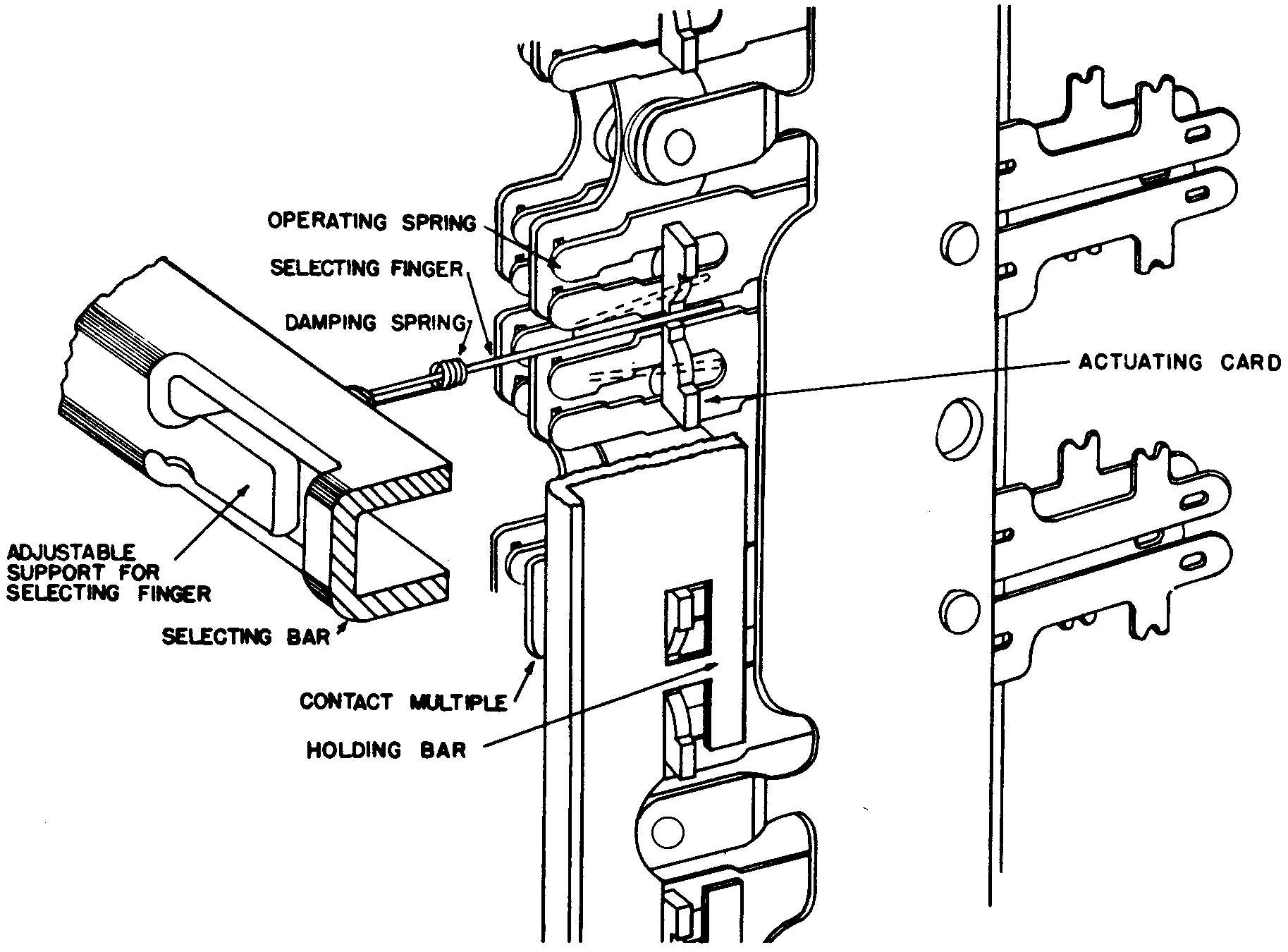
The horizontal bars and attached flexible wire fingers are known as the selecting elements of the crossbar switch (Figure 6-2). Each selecting bar, of which there are five on each switch, can be partially rotated on its axis in either direction by one of two select magnets associated with that selecting bar. Each of the five selecting bars on a switch may thereby either raise or lower its selecting fingers to select one of the ten horizontal rows of contacts.
The vertical unit has ten sets of relay like contact springs and a holding bar. Each set of contacts consists of three to six pairs of normally open or "make" contact springs.
The operating springs have bifurcated (two forked) ends equipped with precious metal contacts. The holding bar is part of a long vertical armature pivoted so as to rotate under control of a holding magnet and a restoring spring.
Each spring assembly is equipped with an actuating card which is constructed to act as a stop limiting the vertical travel of the selecting finger. With the switch normal, one selecting finger is at rest in a horizontal position midway between each pair of spring assembly and in a vertical position midway between the actuating card and holding bar.
It requires a two stage operation to close the contacts at any crosspoint. First a selecting magnet must be operated. This moves a selecting finger either up or down as shown in dotted lines Figure 6-2. Second the holding magnet of the desired vertical is operated. The selecting finger is trapped between the holding bar and the actuating card and operates the selected contacts. The selecting magnet must remain operated until after the holding magnet operates.
Upon the release of the selecting magnet the selecting finger remains held between the holding bar and actuating card, and due to the flexible nature of the finger the selecting bar will return to normal. It may operate again to select crosspoints on other vertical units which are under control of the same selecting bar. The switch may also be equipped with "off normal" spring assemblies which are associated with the selecting and holding magnet and operate when the magnet is energized. They are individual to each magnet and are not dependent upon the two-stage operating cycle described. "Off normal" spring assemblies are provided when it is necessary to give an electrical signal that a selecting or holding magnet has fully operated its associated bar.
Only one selecting magnet on a switch may be operated at one time if the closing of more than one crosspoint on a vertical unit, with the resulting double connection, is to be avoided. More than one connection throughout a switch may exist at the same time without interference after the crosspoints for each have been closed, but those crosspoints must each be closed one at a time. The handling of one connection at a time in a switch, later extended to handling one call at a time in a frame of switches, is a fundamental operating principal of all crossbar systems. It results in freedom from double connections but makes it necessary to reduce to a minimum the time required for a control circuit such as a marker to establish each connection.
Multi-Contact Relay - The use of common control circuits, in crossbar system switching, makes it necessary to connect a host of control leads between the control frame and the switching frames to set up a connection. The simultaneous connecting of these leads is done principally by the multicontact relay which resembles the vertical unit of a crossbar switch. This relay is actually made up of an assembly of two relays on a common mounting. Each half of the relay has its own separate magnet, armature, and spring assemblies. Each assembly may therefore be used as two independent relay or when desired they may be used as one relay by connecting the two magnet coils in multiple. The spring nests consist of normally open or "make" contacts with all springs brought out individually at the front and rear and with no internal multipling of contacts. All springs have split ends and twin contacts.
Multi-Contact Switch - The multi-contact switch is used where continuous operation over relatively long periods of time is desired and where the power to operate a multi-contact relay would be an unnecessary waste. It is essentially a multi-contact relay with the magnets omitted and replaced by a lever or key for manually actuating a plate which takes the place of the armatures. This switch is designed in two types, one with a single lever which will operate all spring sets and the other having two levers, each of which control half of the spring sets as in the case of the multi-contact relay.
"U" and "Y" Type Relays - The "U" and "Y" type relays make up about 80 per cent of all the relays used in the No. 1 Crossbar system. The "U" type relay is capable of handling 24 springs, or twice as many as the "R" type, and requires less power to operate. They are free from chatter and have a non-sticking armature. The "Y" type relay was developed as a "slow release" relay, making use, as far as possible, of the same parts, manufacturing facilities and processes as the "U" type relay.
Interrupter - The power driven interrupter consists of spring assemblies in which contacts are made and broken in accordance with cuttings on a revolving cam. A bar with a roller attached rides on the periphery of the cam and operates the assemblies. The cutting on the cam controls the time interval of the "make" and "break" action of the contact springs.
Timing Devices - The automatic timing devices used in the system make use of condenser timed operating relays and telechron motors. This timing equipment is used to control the operation of the message registers on zone calls initial and overtime periods.
Equipment Nomenclature
Link - The term "link" in the crossbar system is used to designate the connection between the primary and secondary switch on the same frame.
Junctor - A term used to designate the connection extending between frames and terminating on a crossbar switch on each frame. The junctor takes the name of the frame to which it leads.
The paths outgoing from an office link frame and incoming to an incoming frame are called "trunks".
Switch - Assembly of 100 or 200 crosspoints which may contain various combinations of 10 or 20 horizontal paths and 10 or 20 vertical paths.
Vertical - Armature associated with one hold magnet. The number from 0 to 9 and may close any one of 10 crosspoints.
Horizontal or Level - The path selected by a single select magnet.
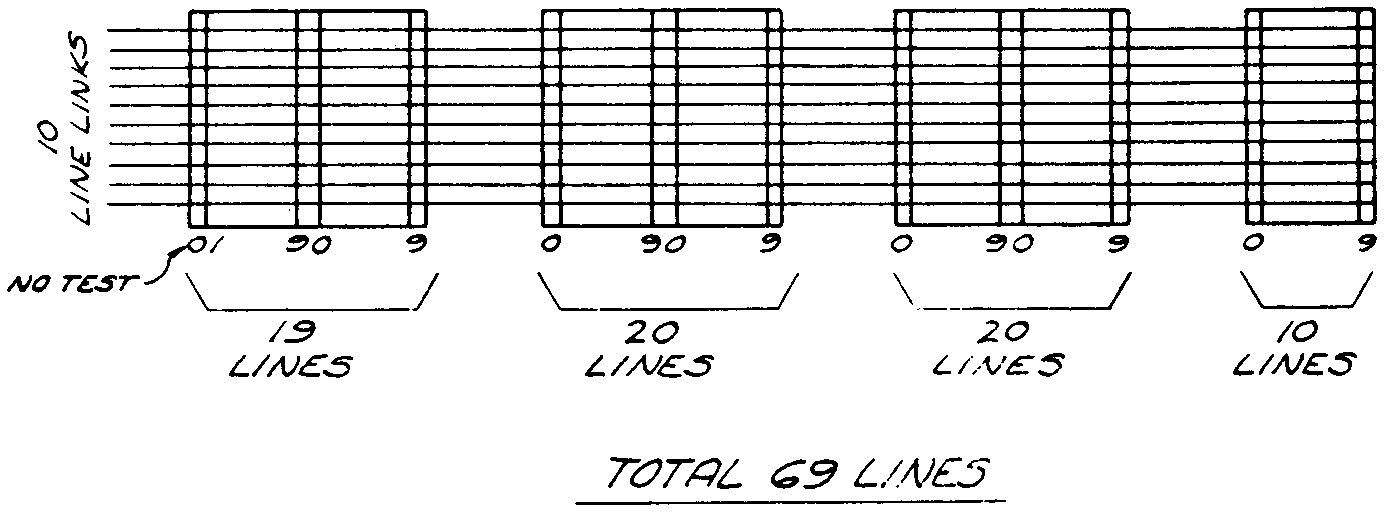
Column - An equipment group of 100 lines, 10 each on the 10 primary switches located in a vertical row on a line link frame.
Horizontal Group - 19 to 69 lines having access to the horizontals of one line link primary switch.
Channel - Combination of two links and a junctor. In originating circuits the channel consists of, (a) district link, (b) office junctor (c) office link.
Terminating channel consists of, (a) incoming
link, (b) line junctor, (c) line link.
Description of Equipment and Functions
From a traffic standpoint the major No. 1 Crossbar dial system frames may be divided into two general classes, originating and terminating, as follows:
Originating Equipment Terminating Equipment
Line Link Frame Incoming Frame Group
District Frame Group Incoming Trunk Frame
District Junctor Frame Incoming Link Frame
District Link Frame Incoming Link Extension Frame
Subscriber Sender Link Frame Terminating Sender Link Frame
Office Link Frame Terminating Sender Frame
Office Extension Frame Terminating Marker Connector Frame
Subscriber Sender Frame Terminating Marker Frame
Originating Marker Connector Frame Number Group Connector Frame
Originating Marker Frame Block Relay Frame
Line Distributing Frame
Line Choice Connector Frame
Line Junctor Connector Frame
Line Link Frame
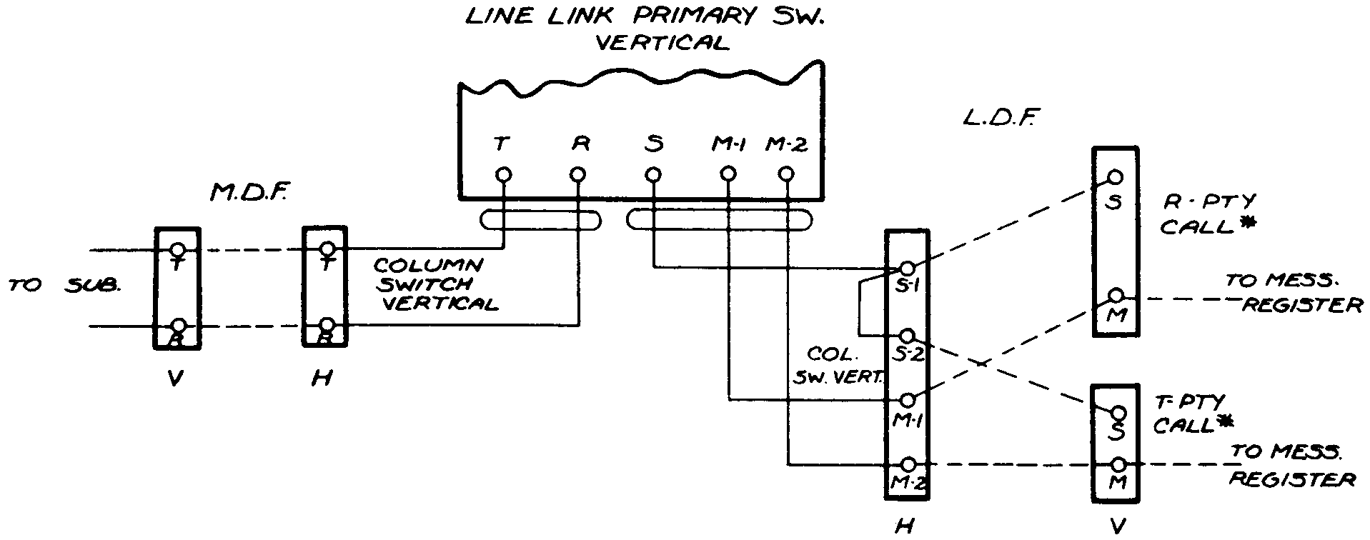
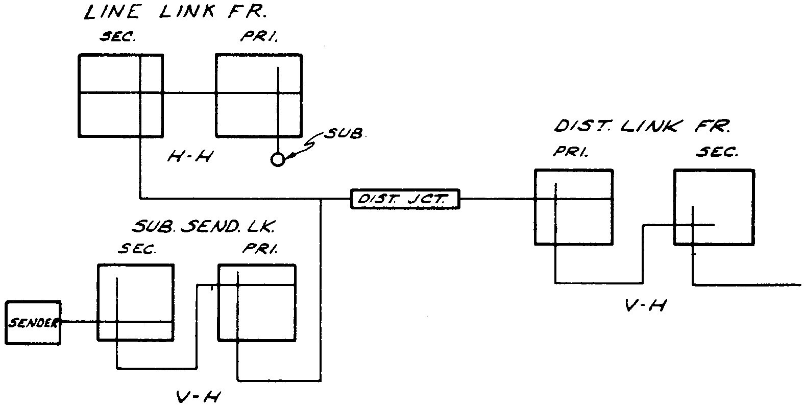
Two distributing frames are also provided. The Main Distributing Frame (MDF) is used for cross-connecting the subscriber and trunk cable pairs to the crossbar frames. The Line Distributing Frame (LDF), provides a means of cross-connecting the line link frames to the terminating marker. This permits any directory number (vertical side LDF) to be assigned to any "line" circuit (Col. -Sw. -Vert. horizontal side LDF) (Figure 6-3).
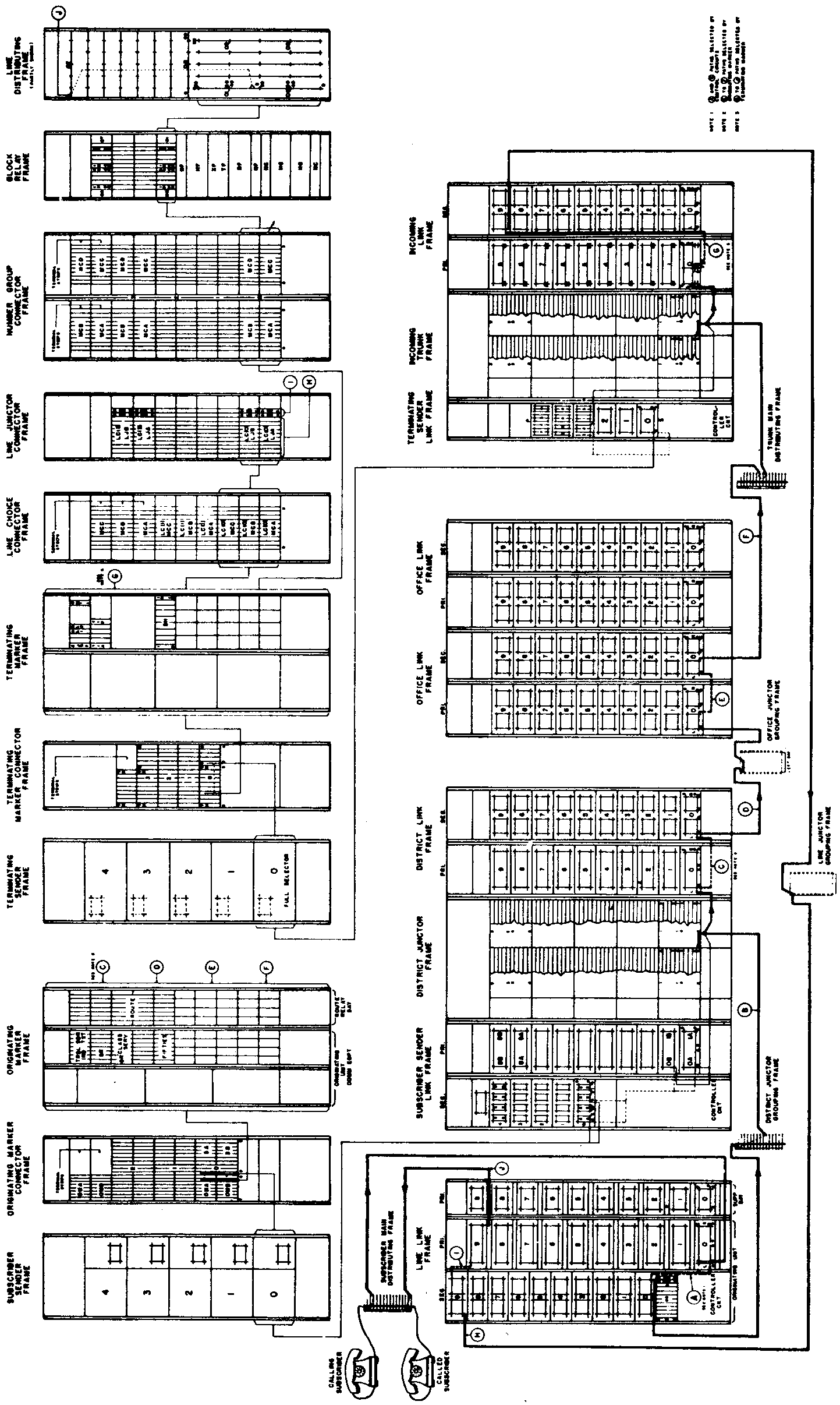
Figure 6-4 illustrates all of the major frames required to complete a crossbar call as well as the path of a call through the equipment frames.
Originating Equipment
Line Link Frame - The line link frame is used for both originating and terminating calls. It connects the customer's lines, which are assigned to verticals of the primary switches, with district junctors for outgoing calls and with line junctors for incoming calls. The assignment of lines to the line link frame is governed by load characteristics, (by the CCS per line for both in and out calls).
The crossbar customer's line is assigned to, and has exclusive use of a vertical of a primary crossbar switch. The primary switch has ten horizontal paths with which this vertical may connect. The ten paths handle all the traffic, both outward and inward for all the lines on a single switch. The first vertical on the first ten primary switches on each line link frame is used to obtain access to busy lines for test and verification purposes. These ten primary switches, plus the ten secondary switches are called the "basic unit". Since the traffic load for nineteen lines does not normally lead the ten horizontal paths, or line links efficiently, additional switches for additional lines are added laterally to form what is known as a horizontal group (Figure 6-5).
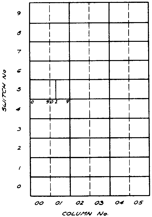
On service orders each line assignment will carry a location number for the line on the line link frame just as it does in the manual office (panel and jack) in the panel office (line group and terminal) and in the crossbar unit (column, switch, and vertical). For example, 0152 means column 01, switch 5 and vertical 2. (Figure 6-6).
Each line link frame has associated with it a "control circuit" whose function it is to recognize a calling line, choose an idle line link and assist in the selection of an idle district junctor and to operate the necessary selecting and holding magnets for connecting these paths together. On a terminating call it assists in setting up the call from the incoming trunk over a line junctor and line link to the called line.
Since a line link controller circuit may provide service to as many as 690 subscriber's lines, it is of the utmost importance that there is always a controller circuit available. As a service precaution, line link frames are arranged in pairs insofar as their controllers are concerned. This arrangement is spoken of as "home" and "mate" controller circuit operation. If a call is delayed in the "home" controller circuit, it will be transferred automatically to the "mate" controller circuit and handled on an "emergency" basis.
District Junctor Frame - The district junctor frame is mounted in the center of the "District Frame Group", the subscriber sender link is on the left and the district link frame is on the right. The district junctor frame is used to mount the relay equipment which provides talking battery and supervision for the calling subscriber and controls the operation of the subscriber message register on calls dialed directly by the subscriber. Each frame will care for the 100 district junctors of the associated district link frame. The subscriber sender link frame provides access for these district junctors to subscriber senders, and the district link frame access to office junctors. (Figure 6-7). The district junctors are multipled to 2, 3, 4, 5, 6, or 7 line link frames as indicated by the traffic requirements.
The coin district junctors, in conjunction with a coin control circuit, collect or refund coins depending on whether or not the called party answers. Non-coin district junctor circuits can be arranged in conjunction with zone registration equipment to make additional charges for calls outside of the local charge zone or area.
District Link Frame - The district link frame also uses the primary-secondary arrangement of crossbar switches, each frame being equipped with ten 200 point primary switches and ten 200 point secondary switches.
The district junctors, which originate at the line link frames, terminate on the horizontals of the district link primary switches, ten junctors per switch. Further, the horizontals of the primary switches are continuous across each switch. 'Those on the secondary switches are cut (split) between the 10th and 11th verticals.
In addition to the primary and secondary switches, the district link frame is equipped with multi-contact relays. The relays, located at the top of the district link frame, are used by the originating marker to gain access to the links and junctors of the district link frames.
Subscriber Sender Link Frame - The subscriber senders are selected for each call by the subscriber sender link frame. This frame consists of primary and secondary switches whose function it is to connect an idle subscriber sender to the particular district junctor which has been selected for a given call. Since this frame must function before the subscriber begins to dial, and before the originating marker is connected, it is provided with a control circuit. The control circuit assists the line link control circuit in selecting the district junctor to be used on each outgoing call. It also determines which senders are available for use for each particular call.
An emergency control circuit is provided for use with any subscriber sender link frame. It can be connected to any one of the subscriber sender link frames by means of manually operated switches located directly above each regular controller cabinet.
Each subscriber sender link frame can handle a maximum of 100 district junctors and 10 subgroups (10 senders each) or 100 originating senders.
Office Link Frame - Each office frame consists of a unit or bay of ten primary switches and ten secondary switches. All the switches are of the 200 point type.
Two hundred office junctors, originating on the secondary switch verticals of the district link frames, terminate on the vertical units of the office link frame primary switches. The two hundred links (left and right) originate on the office link frame primary switch horizontals and terminate on the secondary switch vertical units.
This arrangement makes it possible for any district junctor to obtain connection to as many as 4000 trunk locations (20 office frames with extensions time 200 trunks).
The outgoing trunks, which appear on the horizontals of the office link frame secondary switches are cabled to the main distributing frame. Here they can be cross-connected by jumpers to a local or underground trunk cable, to reach the various exchange areas.
Office frames are always used in pairs, and it is required that trunks to a given exchange be assigned to a pair of office link frames. This insures, that if a trouble condition occurs on one of the frames of the pair, a call to a given central office will be completed over a trunk available on the second office link frame.
Office Extension Frames - When the number of office frames exceeds ten and it is desirable to operate more than 200 trunks per pair of frames, extension frames must be provided. Extension frames consist of an additional group or bay of ten 200 point switches which are installed adjacent to the regular secondary switches of each office frame. The office link circuits, the verticals are multipled giving each trunk location access to all the links.
Subscriber Sender Frames - Each subscriber sender frame mounts five senders numbered from the bottom up, "0" to "4", equipped in numerical order. The ten senders of the two adjacent frames normally make up a sender subscriber group.
The subscriber senders of the crossbar system are similar to and perform much the same functions as those of the panel system, except that they do not control the setting up of the paths between the calling line and the outgoing trunk. On calls to panel and crossbar offices control of the incoming and final selections in the distant office will be on a revertive pulsing basis. In the case of a crossbar distant office, selections will require the use of full selector terminating senders. In panel distant offices the control remains with the originating sender for the entire operation. Calls to manual offices are handled on a call indicator or call announcer basis in the same manner as formerly handled by panel subscriber senders.
Originating Marker Connector Frame - Each originating marker connector frame will accommodate three connectors which connect subscriber and key pulsing senders to origination markers.
Each connector circuit will serve a maximum of ten subscriber senders, or a maximum of eight subscriber and key pulsing senders combined. These may be connected to a minimum of two or a maximum of eight markers.
Originating Marker - The originating marker circuit receives information from the originating sender which it decodes and then returns information to the sender for controlling selections at the terminating end. The marker also selects a trunk to the desired office and establishes a path from the district junctor to the selected trunk as well as transmitting talking selection, charge or non-charge, and party information to the district junctor.
The origination markers are arranged for maximum of 24 subscriber classes and one operator class of service per marker group. A maximum of 8 markers per group may be provided. A group of markers may be associated with a maximum of 20 district frames.
The number of markers required for traffic is based on the originating office busy hour calls plus the key pulsing calls.
A few features and limitations of the originating markers follows:
a. The marker has a capacity for 802 possible codes including zero and permanent signal.
b. The maximum capacity of the originating marker when trunk groups are subdivided is as follows:
30 trunk groups with 2 first choice subgroups -1 route relay.
3 trunk groups with 3 first choice subgroups -2 route relays w/common.
3 trunk groups with 4 first choice subgroups -2 route relays w/common.
3 trunk groups with 2, 3, 4, 6, or 12 -first choice subgroups -2 route relays.
All trunk groups may or may not have a common subgroup in addition to above.
c. Each marker is equipped with a route relay bay arranged for 100 route relays (50 multi-contact relays). Supplementary bays may be added each of which will care for 100 additional route relays.
Terminating Equipment
Incoming Frame Group - The first frames encountered in handling incoming calls are known as the incoming frame group. Similar to the district frame group, they employ three frames: a terminating sender link frame which is always installed to the left of an incoming trunk frame, and an incoming link frame which is mounted to the right of the incoming trunk frames.
Incoming Trunk Frame - The incoming trunk frame provides a location for the relay equipment associated with the incoming trunk circuit. Its functions are to ring the called party's bell, to recognize removal of receiver from switchhook by the called party, to furnish talking battery, and to maintain called party supervision during conversation. In addition, it returns overflow or line busy indications to the calling subscriber in case the call cannot be completed.
Each incoming trunk frame can handle 100 trunks, (5 groups of 20) of the full selector type. Larger size trunks (more relays per circuit) will occupy more space on the frame so these extra circuits will be placed on the supplementary frame.
Incoming Link Frame - The incoming link frame differs from the district link frame in that it is provided with a different type of primary switch, equipped to connect 16 trunks instead of the usual 10.
As ten primary switches are provided, each incoming link frame can therefore connect to 160 incoming trunks. Since each incoming trunk frame can mount a maximum of only 100 trunks, the extra 60 trunks are located on an additional incoming trunk frame. This frame is known as an auxiliary incoming trunk frame, and mounts a maximum of 100 incoming trunk circuits, which will connect through the primary switches of several incoming link frames.
Each primary switch has twenty, ten left and ten right links, going to the secondary switches in a vertical to horizontal spread arrangement.
Multi-contact relays located above the switches on the incoming link frame assist the terminating marker in the selection of the crosspoints on the primary and secondary switches of the incoming link frame.
Terminating Sender Link Frame - The terminating sender link frame connects an idle terminating sender, of the proper type to an incoming trunk for the handling of an incoming call.
The terminating sender link frame is arranged to mount three 100 point 6 wire primary and three 100 point 6 wire secondary crossbar switches together with the associated control equipment.
The control circuits of a pair of link frames are arranged to work on a mate frame basis to care for emergencies.
Terminating Sender Frame - The terminating sender receives information from the originating subscriber sender, from key pulse sender or from dialing trunks. This information is converted by the sender into the called number and passed to the terminating marker.
The terminating sender frame is arranged to mount five senders. The top three positions (2, 3 & 4) will mount full selector senders only while the bottom two positions (0 & 1) will mount either full selector or "B" senders.
Terminating Marker Connector - The terminating marker connector selects an idle terminating marker and connects the sender to the marker.
Each connector frame will care for four marker connector circuits, associated control and alarm relay equipment common to these circuits, together with a location at the top of the frame for a maximum of the two "B" position finder units, required when the office unit is served by a local "B" switchboard.
One connector circuit will consist of from 7 to 15 multi-contact relays. The number varies with the number of terminating markers and the number of senders associated with connector.
Terminating Marker Frame - The terminating marker frame is used to register the called number it receives from the terminating sender and from the translation of that number, locate and test the called line, and control the selection and closure of a path from the incoming trunk through the incoming link and line link frames to the called line.
The number of terminating markers provided in an office will vary from two to ten, depending on the total number of terminating busy hour calls the markers will be required to handle.
When a marker is seized by a sender it must determine, from the number that has been dialed, the correct number group connector to operate, and also the correct 100 block and 20 block relays to operate in the number group. This process is known as decoding, because the decimal directory number received, must be translated in terms designating a number group, a 500 group relay, a 100 block relay, and a 20 block relay. The marker can be arranged to test twenty lines at one time.
Number Group Connector Circuit - The 10,000 numbers in a given office are divided into "number groups". A number group consists of a series of numbers into which all the terminating markers have access, but only one at a time. The size of a number group depends upon the amount of terminating traffic delivered to the numbers. Number groups will never be smaller than 100 numbers and are furnished in increments of 100 numbers up to a maximum of 2500 numbers.
The terminating marker obtains access to a particular number group through a number group connector circuit composed of equipment on a number group connector frame and block relay frame.
It is impractical to build a marker that is able to recognize ten thousand individual indications, and it is, therefore, arranged so that in conjunction with the number group connector and block relay frames it may locate and test the lines in blocks of twenty numbers each, selecting a block of twenty and ultimately the particular one of that block of twenty corresponding to the called number.
The possible 10,000 subscriber numbers of the office are arranged in blocks of twenty, and a 20 block relay (TB) is provided for each subgroup. There may be as many as 500 of these 20 block relays in an office, and, to simplify the selection of the desired one they are grouped into sets of five and operated through a 100 block relay (HB) also located on the block relay frame. Several of the 100 block relays are formed into a "number group" and by means of a number group connector; can be temporarily connected to any one of the terminating markers.
Block Relay Frame - The block relay frame, besides mounting the hundred and twenty block relays associated with 800 lines, is equipped with cross-connecting fields for passing additional line information to the marker.
One field, the "NF", is used to cross-connect the subscribers number to the line choice using one of the following punchings (a) RF punching if the line is ring party, individual line, or the last line of a PBX hunting group. (b) TF punchings if the line is a tip party of a party line. (c) HF punching if it is the first or an intermediate line of a PBX group. (d) JF punching to indicate "jump hunting". (e) ANF punchings for line overflow registrations.
The other cross-connecting field (NC) associated with each number is used for (a) quarter choice location, (b) horizontal group location for the called number.
Another cross-connect which is not associated with the block relay frame is required to give the marker complete information regarding the subscriber line. This is the NS lead which is run on the LDF. It cross-connects the subscriber's number to the Column - Switch - Vertical.
Route of Call Through No. 1
Crossbar Equipment (Figure 6-4)
Line Link Functions - When a subscriber lifts the receiver a line relay associated with the line link frame primary switch vertical to which the line is connected operates. The operation of the line relay notifies the line link controller that a call is being originated. The controller identifies the calling line by determining the horizontal group, vertical column, and vertical file in which the line is located.
District Junctor Selection - It also connects itself to one of several sender link controllers with which the line link frame is associated. The two controllers function together to select an idle district junctor. The selection is made from one of the groups of fen district junctors which has an idle line link back to the calling line and an idle sender link to a sender subgroup which has an idle sender. District junctor groups having at least two idle junctors are preferred.
Subs Sender Selection - Coincident with the selection of a district junctor, the sender link controller is selecting an idle sender. This selection is made from subgroups having an idle sender link to the selected district junctors. Preference is given to those subgroups having two or more idle senders.
Dial Tone - Following these selections, crosspoints are closed on the line link frame primary and secondary switches connecting the customer's line to a district junctor and at the same time crosspoints are closed on the sender link primary and secondary switches to connect the district junctor to a sender. Over these paths the tip and ring of the customer's line are now connected to a subscriber's sender. The sender sends out dial tone, indicating that it is ready to receive dial pulses.
District Link Frame Indication - The sender also registers the number of the link frame involved, receiving this information from the sender controller.
Dial - The subscriber now dials the office code and directory number of the called subscriber. The sender counts the dial pulses and registers all digits dialed on the register switch.
Originating Marker Selection - As soon as the office code is registered, the sender signals the originating marker connector which connects the sender to an idle originating marker cutting through a large number of leads over which the sender and marker exchange information.
Marker Decoding - The marker receives from the sender the district frame number and the office code dialed. It decodes this information and sends back to the sender the information it needs to complete its part in handling the call.
Marker Test of Trunks - From the route relay assigned to the office code the marker determines the pair of office frames on which the trunks to the desired office are located. The route relay also provides information as to the trunk level and the start and stop test points within that level. Through connector relays at the office frame the marker gains-access to the specified trunk locations, tests and selects an idle trunk.
Marker Channel Test - The marker gets access to the office links that serve the selected trunk through connector relays at the office link frame. It also gets access to the district link that serve the district junctor and office junctors leading to the office frame on which the selected trunk is located. Access to both the office links and office junctors is obtained through the district frame connector relays. From this combination of links and junctors the marker selects an idle district link which has access to an idle office junctor which in turn has access to an idle office link which appears before the selected trunk.
Channel Closure - The marker now operates the select and hold magnets on the district and office link frames necessary to complete this channel from the district junctor to the selected trunk. This also provides a path from the subscriber sender to the trunk since the sender was cut through to the district junctor. The marker now has completed its functions and releases.
Incoming Trunk in Terminating Office - This outgoing trunk is connected to an incoming trunk in the terminating office.
Terminating Sender Selection - The incoming trunk when signaled by the subscriber sender, will cause the terminating sender link controller to select an idle terminating sender and to connect it to the incoming trunk.
Called Number Transferred to Sender - The two senders are now connected. The called number is transferred from the subscriber sender to the terminating sender where it is recorded on a register switch. With this information transferred the originating sender has completed its functions and releases.
Terminating Marker Selection - The terminating sender now signals the terminating marker connector which connects an idle terminating marker to the sender cutting through the leads over which information is passed. The marker receives the called number and the incoming frame number from the sender.
Block Relay Selection - The terminating marker translates this number as being in a block of 100 numbers and finally as being in one of five blocks of twenty lines in the selected block of 100 numbers. By means of cross-connections, the marker will then operate its marker connector relays in the proper number group, the proper hundreds block relay and through it the twenty block relay associated with twenty consecutively numbered lines, one of which is the called number.
Called Line Test and Location - The twenty block relay operates and cuts through to the marker a number of control leads which give the necessary information regarding the line and its location. The marker then tests the called line to determine whether it is busy or idle. If busy, the marker will set the incoming trunk so that the calling subscriber will receive busy tone. (The marker will then release immediately).
Line Choice Selection - If idle, the marker will determine from cross connections on the block relay frame whether it is an individual or PBX line, whether tip or ring party ringing is required, in which line choice, on which one of the four line link frames of the choice and in which horizontal group of the line link frame the called line is located.
Marker Channel Test and Closure - From the line location information, the marker, by way of a line choice connector and line junctor connector, is able to test the line links that serve the horizontal group in which the called line is located. Knowing the incoming link frame to which it must connect, the marker tests the line junctors between this frame and the line link frame. At the incoming link frame, connector relays give the marker access to the links available to serve the incoming trunk. From this combination of links and junctors, the marker selects an idle incoming link with access to an idle line junctor which in turn has access to a line link serving the horizontal group in which the called line is located. The marker will then operate the primary and secondary select and hold magnets on the line link and incoming link frames necessary to close this path between the incoming trunks and the called subscriber.
Apply Ring - The marker also sets the incoming trunk to apply proper ringing to the called line. The marker and terminating sender now release.
Line Supervision - The incoming trunk applies ringing current to the called line and, when the called party answers stops, the ringing and signals the district junctor that the called party has answered, so that the correct charge may be made. The calling subscriber may now talk to the called subscriber, the district junctor applying talking battery to the calling subscriber, and the incoming trunk to the called subscriber. At the end of the conversation, the two parties will hang up, and all circuits will release.