 |
This new web page addition to my website was inspired by this email I received in April 2002 from Brian M. Slator:
Hi,
Just a quick note to inquire whether you have a pointer for me. I worked on the Soo Line railroad in the late 70s on a line crew, which maintained/repaired the railroad's private/internal phone system, connecting depots and dispatchers.
After much searching, including your very extensive and nicely done site, I have been able to find nothing directly relating to the history and development of these phone systems. I was told at the time that the railroads were among the first to switch from telegraph to telephone, much before the rest of the country. But no "history of the telephone" or "history of the railroad" even mentions this, much less expanding on it. I'd like to know more about this <snip>.
Thank You,
Brian Slator
Professor Computer Science Department
North Dakota State University Fargo, ND 58105 USA
In response to me posting Brian's inquiry on the list serves of the TCI and ATCA clubs, I received the following information, photos and schematics from club members:
Telephone Train Dispatching and the
Western Electric Type 60 Selective Signaling SystemBy Paul Wills
(Please visit Paul's website "The Cedar Knoll Telephone and Telegraph Company" for some
great photos and sound files of his equipment. Steph Kerman also contributed to this article)This article originally appeared in the November issue of Singing Wires, the official publication of Telephone Collectors International, Inc.
Bruce Crawford, in the October Singing Wires, provided a very complete description of railroad telephone equipment. Of course, as Bruce reported, the most unique characteristic of these sets is the lack of a ringer or magneto. There were several signaling systems, however, that were designed to fill the unique requirements of a railroad communications system. As a follow-up to Bruce�s article and because this equipment shows up at phone shows and antique shops from time to time, it may be appropriate to describe the Western Electric No. 60 Selective Signaling System in some detail.
Perhaps no other invention has done more for the railroad industry than electrical communications. Prior to the invention of the telegraph, the use of schedules and a complicated set of operating rules prevented interference between trains. This worked as long as all of the trains were running properly. A delay to one train, however, could adversely affect the operation of the entire railroad as opposing trains either had to wait for the late train to pass the scheduled meeting place or proceed slowly while a flagman walked ahead prepared to stop the late train.1 With the adaptation of the telegraph in the 1850�s it became possible to alter the operation of the railroad to accommodate late trains, extra trains and other unusual occurrences with a much greater degree of safety.
Railroad operations in the early days required many people to be located along the railroad. Agents and Operators were responsible for delivering train orders and other instructions to the train crews who actually ran the trains. In many cases, operators also controlled the switches and signals that directed the trains over the road. These agents and operators reported to the "Train Dispatcher." The Train Dispatcher was responsible for all of the traffic over a given line. The Train Dispatcher had to keep in constant contact with all of the Operators in order to know the status of all the trains on that territory. The Train Dispatcher also had to be able to contact any Operator at any time to give out train orders and other instructions. The telephone or telegraph line that connected all of those people was called a "Train Wire" or "Dispatchers Line."
The telegraph worked well for train dispatching and was used by some lines in the USA until the 1960�s. Other railroads, however, adopted the use of the telephone very early. On December 20, 1879, the Boston, Revere Beach and Lynn Railroad became the first line operate its trains by telephone.2 Use of the telephone was limited, however, due to the lack of the ability to selectively signal one of the many wayside locations that a train wire would serve. A Morse telegraph circuit is always "on" and an experienced operator could pick out his unique call from the constant sound of dots and dashes that filled the room. To hear a call on a telephone, however, the operator had to have the phone to his ear, something that would be quite a problem if that operator wanted to get anything else done. The extreme length of a train wire combined with the large number of stations made coded ringing impractical. The development of a reliable selective signaling system is what made telephone train dispatching practical. (It should be noted that the train dispatcher, was expected to monitor the train wire at all times so the provision of "inbound" signaling was not mandatory.) Development of such equipment started prior to 1910 and by the �teens, several reliable systems were available. This had a dramatic effect on the adoption of telephone train dispatching such that by 1925 the mileage dispatched by telephone exceeded that that was dispatched by telegraph.3
Early selective signaling systems were developed that used DC line battery for operation but the Western Electric No. 60 system, developed in 1916, ultimately became the most widely used selective signaling equipment for U. S. railroads. In addition to the railroads, the No. 60 selector system was also used by pipe lines and public utilities for their private lines. Tone controlled variations could also be found on FAA private lines and even in radio dispatched taxi cabs. Standard Telephones and Cables also marketed this system in throughout the world, with some variations in model numbers and wayside equipment.
In spite of the early date that it was developed, this equipment could still be found in regular use into the early 1980's when it was replaced with DTMF based equipment. There was even a firm in the US that still made the equipment. (General Communications Products) They had bought the manufacturing rights from Western Electric a number of years ago. Recent attempts to locate them have been fruitless.
There are three basic components to the No. 60 selector system; the Key, the Apparatus Case and the Selector. Because the selector is both the heart and "brain" of the system, it will be presented first:
The signal that operates the selector consists of a series of polarity reversals that will be described shortly. Since these signals are capacitively or inductively coupled to the line, the No. 60 selector system is considered an "AC" system, the operating frequency being nominally 3.5 Hz. (One "cycle" would consist of two 143ms "pulses.")
The selector operates not unlike a telephone ringer. Current through the coils works against a permanent magnet driving the armature one way or the other with each half cycle of current. Each operation of the armature causes a code wheel to step one step. However unlike a ringer, the selector armature is biased to the center instead of to one side. The armature drives a double-sided pawl which drives the wheel forward one step for each armature deflection from the center to either side or from side to side, regardless the direction of armature motion..... like a mechanical rectifier in a way. So unlike typical telephone steppers, the count is advanced by each edge rather than by each pulse.
The selector has a 21K ohm coil which is AC coupled to the line either through a 1.25uF capacitor or line coupling transformer. This requires the application of alternations or polarity reversals rather than unipolar pulses. The AC coupling of the selector coil limits the maximum armature holding time during pulsing.... the time before the current decays. As long as the armature is held in either extreme position, the code wheel remains held in place. When the armature relaxes to the center position, the wheel would normally release. Thus, a series of reversals would drive the armature from one side to the other advancing the code wheel. When the reversals stopped for a sufficient period of time the code wheel would be allowed to release and restore to its home position.
Now to make it respond to a unique code: There are holes around the perimeter of the code wheel that line up with each step of the wheel. Code pins are installed in these holes to set the specific code that is to be received. Under the edge of the code wheel is a little holding spring (a pawl in effect) that jumps in and out as the armature operates.
All selectors on the line step in unison. As the code wheel steps, the holding spring jumps in and out stopping each time where a code pin *should* be. If a pin happens to be lined up with the holding spring when the armature relaxes, (due to a pause in the pulse train), the wheel is held in place to wait for the next string of reversals. If no pin is found, the wheel restores back home and is no longer capable of reaching the final ringing position when pulsing of the remaining digits is completed.
It takes 17 reversals to step the wheel up to where it closes the ringing contact. (There are modes that use a higher number of reversals but we won't discuss them.) One fixed pin is located at the 17th position to hold the wheel in place during the ringing phase. Two other pins can be located anywhere between the first and 17th position to set the code.
To send a unique code, the 17 reversals are broken up into three strings of reversals with a short pause between each string. Consider 4-6-7 for example: A pin would be set at the 4th and 10th positions on the wheel.
The dispatcher starts a sending key (we'll get to that later) and sends four reversals out on the line. The wheel steps four times. During the first pause, the armature relaxes but because a pin happened to be in line with the holding spring, the wheel remains in place. Now 6 reversals are sent. Again, during the second pause, the armature relaxes but the wheel remains in place because of the pin in the 10th position. The last 7 reversals step the wheel up to the fixed pin, causing the ringing contacts to close. Now a longer pause occurs to give the ringer a chance to ring. Finally one clearing out pulse steps the wheel beyond the fixed pin and it drops home, stopping the ringer and restoring the selector for the next time.
The bell is local battery powered and the self interrupted contact is capacitor coupled to the line to provide a "ringback" signal to verify to the dispatcher that the call "took."
What would happen if a different code were sent? Take 2-6-9 for example: Two reversals would be sent, the wheel would step two times but no pin would be there for the holding spring so the wheel would return home. The six reversals would step the wheel six times but, again, there's no pin to be held so the wheel restores. The same thing happens for the 9 reversals.
The apparatus case houses the pole changing relay, line relay and filtering equipment. The pole changing relay actually sends the reversals out on the line. The line relay connects the line to the sending equipment for the duration of the ringing cycle. The filtering equipment "rounds" the square wave into a smoother wave form that allows the numerous users to remain on the line without having their ear drums blown out the other side of their heads. (It makes a very pleasing "thumpa thumpa" sound.) Line voltage could be set to several hundred volts depending on the length of the line.
The ringing sequence:
1) The line relay closes applying the voltage to the line. The time between the initial application of line voltage and the first selection pulse is twelve 143mS pulse periods or 1.7 sec. All selectors would respond by taking a single step. Since the first valid digit must be 2 or greater, all selectors would reset during the long subsequent pause. The pauses between strings of pulses are 6 periods or 858mS long so this long initial delay would seem to provide time for any off-normal selectors to restore before a new selection is made.
A short pause and then...
2) The pole changer operates and releases to send the first reversals. The 3.5 Hz rate is sufficient to keep the selector moving back and forth such that the armature in the selector will not pause in the released position. Note that for an odd number of reversals the pole changer may end up operated.
Another short pause and...
3) The pole changer sends the second string of reversals.
4) The pole changer sends the third string of pulses. 17 reversals have now been sent. A long pause now occurs allowing the selected ringer to ring. Note that on the 17th reversal, the pole changer relay is operated. This second long pause is also 12 periods or 1.7 sec for ringing. The total signal sending cycle time is 7.5-8 seconds.
5) After the ringing interval, the pole changer releases, sending out one last reversal to clear out the selector(s). (By setting the codes properly and sending two digit ringing codes, multiple selectors can be operated. A series of 17 reversals with no pauses will ring everyone.)
6) The line relay releases, removing the sending equipment from the line.
There are three basic types of keys that control the sending equipment in the apparatus case:
1) A cabinet of individual windup keys, each with a set of cams to ring one specific station.
2) A lever set type clockwork driven key where the operator selects the code cams by setting two* levers and then pulls a lever down to send the code.
3) An electrically driven commutator based key where the code is selected by pushing two* buttons and operating a "start" button.
On the two selectable keys, the operator would push only two buttons or sets two keys corresponding to the first and last digit in the calling code. The key automatically adds the second digit in the middle.
*There is a third lever or set of buttons used to send codes that use over 17 reversals. Obviously, more pulses allow more unique codes to be sent but there are also several auxiliary functions that the selector can perform when stepped beyond the 17th position.
There are several collectors who have been able to assemble working No. 60 Selective Signaling systems for their own display. Certainly, they are interesting to watch in operation.
The selector relays and selector boxes are relatively common and turn up at phone shows, flea markets and on Ebay. The apparatus cases are quite rare but a unit capable of operating a selector could be easily reproduced with modern components. (Of course, the distinctive "thumpa thumpa" sound would still require a proper filtering network to be designed.)
The sending keys are somewhat rare but show up at railroad memorabilia shows from time to time. The keys could be reproduced with modern components if necessary but, as they used to say in school, "this exercise is left for the interested student."
A big thanks should go to Steph Kerman for his contributions to this article.
1 "The Wire System of a Great Railroad." Pennsylvania Railroad Information for the Public and Employees May 1925: 3
2 Warren H. Hay. "The Beginnings of Telephone Train Dispatching." Railroad History 130 (1974): 55
3 Hay 59.
Click here for schematic using 60 AP Selector
Click here for schematic of No. 62C Selector Apparatus Case Schematic
The following message and photo are from Kenneth Rehor:
I saw your email inquiry about telephone equipment used in railroad applications (it was posted on a telephone history mailing list that I subscribe to). I too am interested in this topic, born from my love of railroad history (particularly western US), and the Bell System. I'm collecting information on the subject with the plan of assembling a little website (or maybe I'll contribute it to David Massey's [Tribute to the Telephone] site). I'd be glad to swap what info I do have.
One book I found to be extremely useful is Western Electric's "Railway Dispatching and Communication Equipment" catalog (a very nice hardcover book) from 1949. It covers everything from dispatcher's selector equipment to telephone sets to cords, jacks, and test equipment. It has tremendous detail in some areas (19 pages of cord specifications!), but little info about actual installations. There are a few wiring diagrams, but it is still a catalog, not field installation instructions.
I have been collecting equipment used in rail stations, and have a few phones, jack boxes (one stamped with Milwaukee Road's initials), and ringers. I have found that railroad books, particularly great photo essay-type books like the ones by my favorite photographers such as Richard Steinheimer, Ted Benson, and Chard Walker, have great pictures showing phone equipment in typical use. I also have a few photos from the Bell Labs archives (from when I worked there).
Two weeks ago I was in the former NWP station in Santa Rosa (California) which was restored and converted into a tourism office for the city. See the attached photo of the dispatcher's desk, complete with vintage WE equipment. Note the transmitter footswitch and battery box inside the bottom left side of the desk, and the 385 jack box on the window pillar.
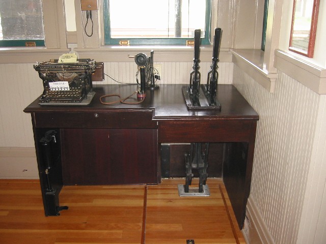
Santa Rosa NWP
Dispatcher's desk, complete with vintage WE
equipment. Note the transmitter footswitch and
battery box inside the bottom left side of the desk, and the 385 jack box on the
window pillar.
Courtesy of Paul Wills
If anyone would like to contribute to this web page, please contact me. I generally do not post other people's email addresses on my website due to spamming problems that can occur from publicizing such information.